

02,Apr,2025
What is the main purpose of a current transformer? + Read More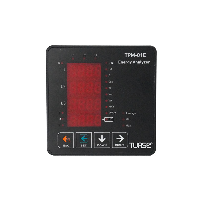


Measures up to 31st voltage harmonic. (TPM-01ES and TPM-01ESH)
Measures up to 31st current harmonic. (TPM-01ES and TPM-01ESH)
Supports 3P4W connections.
RS485 ModbuS RTU ITPM-01ES and TPM-01ESH)
4x4 digit LED display.
Shows active [P1, P2, P3) powers of each phase
Shows reactive (Q1,Q2,Q3 inductive or capacitive) powers of each phase.
Shows apparent (S1,S2,S3) powers of each phase.
Shows power factors (PF) and Cosφ values of each phase.
It shows the minimum, maximum and average values of phase-neutral and phase-phase voltage (V).
It shows the current (l1, 12,13) values for each phase.
It shows the total import and export active (∑kWh) energy.
It shows the total inductive and capacitive reactive (∑kVArh) energy.
Digital Input. (TPM-01ESH)
Relay output (adjustable) (TPM-01ES and TPM-01ESH)
Voltage and current irregularity. {TPM-01ES and TPM-01ESH)
It shows the demands. (TPM-01ES and TPM-01ESH)
You can delete the energies and demands.
Menu password protected.
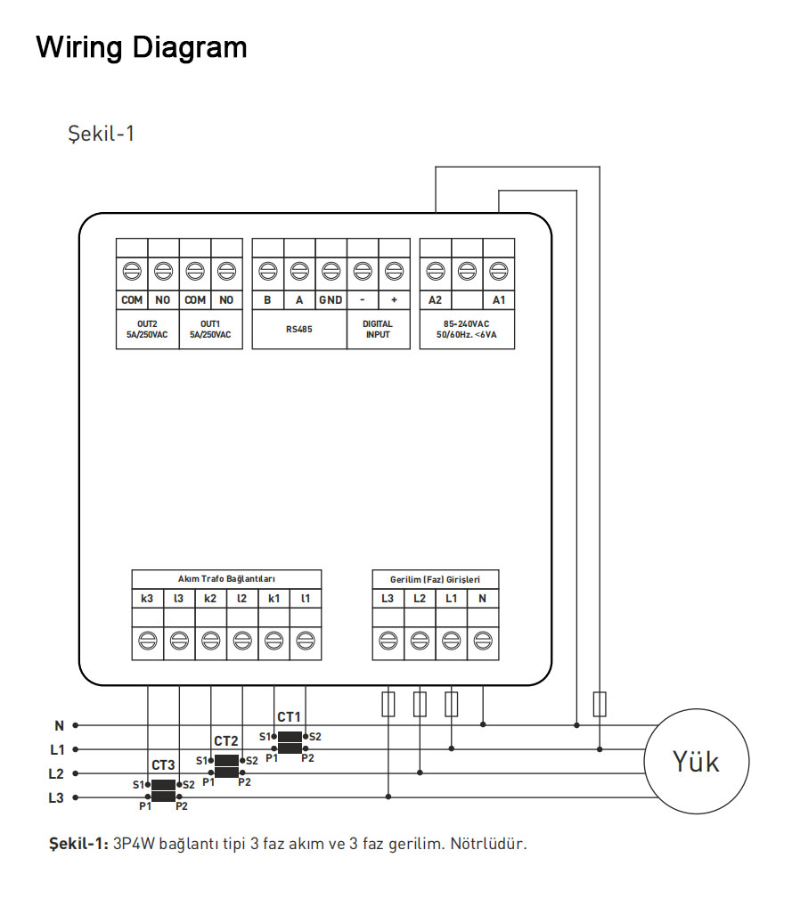
Akim trafosun deǧerinin sistemden cekilen maksimum akimdan yüksek olmasina dikkat ediniz.
Akim trafosunun klas sinifi lclass, klas, cl, kl yazabilir.) 0,5 tavsiye edilir
Akim trafosu cikis uclarin baǧlarken karisiklik olmamasl icin her faza ayri renklerde kablo kullanin veya kablolari numaralandirn.
Akim trafosu cikis uclarina baǧlanan kablolar! yüksek gerilim hattindan uzak yerlerden geciriniz.
Akim trafolarinin sarsilmamasl icin baraya, kabloya veya raya sabitleyiniz.
Use the device in accordance with the instructions given by us.
In order to prevent damage to the LCD screen, make sure that it does not receive direct sunlight.
After the device is installed, leave at least 5 cm of space behind it.
Secure the device to the front cover of the panel with the equipment provided with it so that it does not shake.
Make sure that the panel on which the device operates does not operate in a humid environment.
Include a switch or circuit breaker in the installation.
Keep the switch or circuit breaker close to the device and in a place that the operator can easily access.
There should be no electricity in the connection cables during installation.
In input and output lines that are not connected to the network, screened and twisted cord cables should be used.
These cables should not be passed near high power lines and devices.
Installation and electrical connections must be made by technical personnel in accordance with the instructions in the operating instructions.
Power cables must comply with the requirements of lEC 60227 or lEC 60245
Turn off the power of the device and disconnect it from the connections. Clean the body of the device with a slightly damp or dry cloth. Do not use conductive or other chemical substances that may damage the device as cleaning agents. After cleaning the device, make the connections and power up the device and make sure it is working.
TPM-01E/ES and ESH energy analyzer measures voltage, current, cosφ, active power, reactive power, minimum and maximum values and energy of the load or loads in the system. Measures demand, current and voltage harmonics up to the 31st harmonic. (Only TPM-01ES and TPM-01ESH)
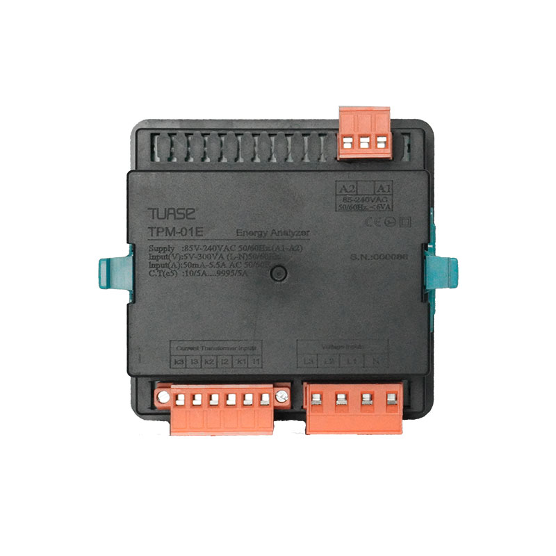
Read the warnings before powering up the device. Make the device connections in accordance with the connection diagram. When the device is first powered up, Figure-3 appears on the screen during startup. First, enter the current transformer ratio and voltage transformer ratios (if measuring from medium voltage) from the settings menu.
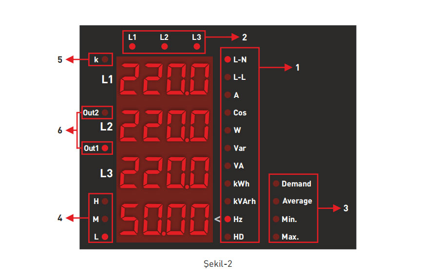
1-Shows the unit of the value shown on the screen.
2-Shows which phase the value belongs to. (L1, L2, L3)
3-Shows the type of the value shown. Minimum, maximum, average and demand.
4-Shows the magnitude of the current value drawn from the system.
5-When the value shown on the screen is greater than 9999, the "k" LED lights up.
6-Shows the relay status.
| Working Voltage | 85V-240V AC |
| Working Frequency | 50/60 Hz |
| Working Power | <10VA |
| Working Temperature | -20℃.....55℃ |
| Voltage Input | 5V -330V AC |
| Voltage Measurement Range | 5V -330kV |
| Current Input | 10mA-5.5A |
| Current Measurement Range | 10mA-5.500A |
| Voltage, Current Accuracy | %±0.5 |
| Active Accuracy | %±1 |
| Reactive Accuracy | %±2 |
| Supported Connection | 3P4W |
| Current Transformer Ratio | 1....1000 |
| Voltage Transformer Ratio | 1.0....999,9 |
| Harmonic Voltage | 3-31 |
| Harmonic Current | 3-31 |
| Communication | RS485 MODBUS RTU |
| Baudrate | 1200bps-38400bps |
| Stop Bit | 1 veya 2 |
| Parity | None, Even, Odd |
| Indicator | 4 pieces 4 Digit 14mm LED Display 24 pieces LED |
| Contact Output | 2 x 3A/250VAC (Resistive Load) |
| Digital Input | 1 x 9V-24VDC |
| Weight | <300Gr. |
| Protection Class | IP41(Front Panel), IP20(Body) |
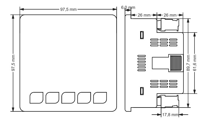
| Panel Hole Dimensions | 91mm×91mm |
| Connection Type | Terminal block connection |
| Cable Diameter | 1.5mm² |
| Mounting | Mounting on the front cover of the panel |
| Working Altitude | <2000metre |